

Pneumatic Wafer Butterfly Valve
All products undergo factory pressure testing: All supercritical products can provide factory pressure test reports.
Key words:
Classification:
Product Details
Basic Information
| Product Model | D671X-10/16Q |
| Product Name | Pneumatic Wafer Butterfly Valve |
| Valve Body | Ductile Iron DI |
| Valve Seat | EPDM Rubber |
| Disc | Ductile Iron DI |
| Valve Shaft | 45 |
| Drive | Pneumatic |
Product Features
(1) All products undergo factory pressure testing: All products can provide factory pressure test reports.
(2) High-performance valve seat rubber: The rubber content of the valve seat is 50%, with a switch life of over 30,000 times.
(3) Soft-backed valve seat: Compared to hard-backed valve seats, the soft-backed valve seat has a wider contact surface with the pipeline flange, better sealing performance, and does not require a special flange for the butterfly valve.
(4) Axial sealing: The valve shaft is supported by four oil-free bearings, with a dual sealing structure of O-ring and oil seal, resulting in lower torque and reliable sealing; for large diameter valves above DN350, the upper and lower shaft holes use a packing box design, achieving sealing through compression of the packing.
(5) Surface coating: Uses epoxy resin powder coating, with strong adhesion, good weather resistance, suitable for indoor and outdoor use.
(6) Pneumatic actuator: The pneumatic actuator uses a double-piston rack structure, with precise engagement, high efficiency, and constant output torque. The cylinder body is made of extruded aluminum alloy, with high strength and hardness. It uses low-friction materials for sliding bearings, resulting in low friction coefficient, flexible rotation, and long service life.
(6) Valve shaft blow-out prevention structure design: The pinless butterfly valve adopts a blow-out prevention structure design, allowing for the replacement of the electric actuator under pressure.
(8) Pinless structure, soft-backed valve seat, installation does not require any special equipment, facilitating maintenance and replacement of parts.
Technical Parameters
| Caliber Range | DN40-DN1200 |
| Nominal Pressure | PN10/PN16 |
| Applicable Temperature | -20~120°C |
| Applicable Medium | Clean water and neutral liquids |
| Application Fields | Municipal construction, water conservancy projects, electricity, water supply and drainage, water treatment |
Implementation Standards
| Name | Reference Standards |
| Design and Manufacturing |
GB/T 12238 |
| Structural Length |
GB/T 12221 |
| Pressure Test Standards |
GB/T 13927 |
| Upper Flange Size |
ISO 5211 |
| Side Flange Size |
CLASS150/PN10/PN16/10K |
Optional Configurations
| Valve Body | Valve Seat | Disc | Valve Shaft | Drive |
| CI/DI/WCB/CF8/CF8M/Copper |
NBR/EPDM/SI/PTFE/VITON/Wear-resistant/Heat-resistant/Food-grade EPDM |
DI/WCB/CF8/CF8M/C954 (With pin/Without pin/Milwaukee) |
45/420/304/316/431 (Through shaft with pin/Double half shaft/Through shaft without pin) |
Handle/Worm Gear/Electric/Pneumatic |
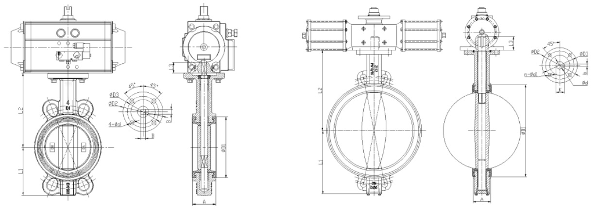
Size Information
| DN | A | D1 | L1 | L2 | L3 | B | φD2 | φD3 | N-φd | |
| 1.5" |
DN40 |
34 |
62.5 |
55.5 |
111 .5 |
25 |
9 |
65 |
50 |
4-8 |
| 2" |
DN50 |
43 |
80 |
72 |
132 |
25 |
9 |
65 |
50 |
4-8 |
| 2.5 |
DN65 |
46 |
95 |
86 |
138 |
25 |
9 |
65 |
50 |
4-8 |
| 3" |
DN80 |
46 |
113 |
96 |
153 |
25 |
9 |
65 |
50 |
4-8 |
| 4" |
DN10 |
52 |
135 |
108 |
167 |
28 |
11 |
90 |
70 |
4-10 |
| 5" |
DN125 |
56 |
163 |
125 |
184 |
28 |
14 |
90 |
70 |
4-10 |
| 6" |
DN150 |
56 |
190 |
138 |
195 |
28 |
14 |
90 |
70 |
4-10 |
| 8" |
DN200 |
60 |
244 |
170 |
236 |
33 |
17 |
125 |
102 |
4-12 |
| 10" |
DN250 |
68 |
298 |
209 |
266 |
33 |
22 |
125 |
102 |
4-12 |
| 12" |
DN300 |
78 |
350 |
236 |
305 |
33 |
22 |
125 |
102 |
4-12 |
| 14" | DN350 | 78 | 397 | 271 | 327 | 45 | 22 | 125 | 102 | 4-12 |
| DN | A | D1 | L1 | L2 | L3 | φd | φD2 | φD3 | n-φd1 | N-b | K | ||||||||||||||||||||||||||||||||||||||||||||
| 16" | DN400 | 85.5 | 456 | 320 | 403 | 52 | 33.15 | 175 | 140 | 4-18 | 1-10 | 36.2 | |||||||||||||||||||||||||||||||||||||||||||
| 18" | DN450 | 103 | 516 | 351 | 415 | 52 | 38 | 175 | 140 | 4-18 | 1-10 | 41 | |||||||||||||||||||||||||||||||||||||||||||
| 20" | DN500 | 125 | 556 | 386 | 466 | 64 | 41.15 | 175 | 140 | 4-18 | 1-12 | 44.2 | |||||||||||||||||||||||||||||||||||||||||||
| 24" | DN600 | 151 | 658 | 446 | 525 | 70 | 50.65 | 210 | 165 | 4-22 | 1-16 | 54.7 | |||||||||||||||||||||||||||||||||||||||||||
| 28" | DN700 | 164 | 771.5 | 520 | 618 | 95 | 63.35 | 300 | 254 | 8-18 | 2-18 | 71.4 | |||||||||||||||||||||||||||||||||||||||||||
| 32” | DN800 | 189 | 811 | 580 | 665 | 95 | 63.35 | 300 | 254 | 8-18 | 2-18 | 71.4 | |||||||||||||||||||||||||||||||||||||||||||
The above information is for reference only. Mylte Valve reserves the right to update the design without prior notice. Please contact your sales representative before placing an order.
Related Products


Product Consulting
If you are interested in our products, please leave your contact information, we will contact you as soon as possible, thank you!

The company has sophisticated equipment, the use of advanced manufacturing technology, perfect detection means, strong production capacity. The company's main products: butterfly valves, gate valves, ball valves and other products, are widely used in power plants, petroleum, chemical, pharmaceutical, gas, food, paper, water supply and drainage, air conditioning, piping systems and other fields.
Contact Us
No.5 Road, Xiaozhan Industrial Park, Jinnan District, Tianjin